7.0 KiB
Return to Ritherdon: Relay
Relay is one of three smaller projects which make-up the 'Personal Flash in Real-Time' -- which is one artwork with the main 'Return to Ritherdon' project.You should view the three smaller projects as one project. And, for the purpose of this documentation, I will refer to 'Personal Flash in Real-Time' as a system instead of an artwork.
For more information on the 'Return to Ritherdon' project, use the following link:
'Personal Flash in Real-Time': Project Overview
The overall system ('Personal Flash in Real-Time') consists of three separate/smaller projects. You should not view them as individual pieces within the overall project. From an artwork point-of-view, 'Personal Flash in Real-Time' is one piece. The name of the software projects are 'Light Meter' (which is this one), 'Midpoint' and 'Relay'. All three projects reside in their own git repositories. You can find the repositories at the following links:
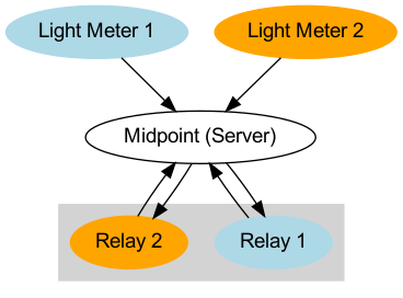
The (technical) aim of the project is to turn a set of lights on at the gallery when the welding machines are active in the welding booths at Ritherdon. The solution we arrived at was a three-stage process. The stages are as follows:
- Monitor the light levels in the welding booths at Ritherdon and send that information to a sever (Light Meter).
- Receive the light readings and store them in a database and make them available for others to access (Midpoint).
- Have the lights installed at the gallery connected to wi-fi enabled relays which request the latest light readings from the server. If the readings are above a certain threshold, have the light in the gallery turn on (otherwise, turn off). The relays are responsible for turning the lights on and off (Relay).
Each step should require no human intervention.
For more information on how each project accomplishes its task, please use the (repo.) links above. Otherwise, here is an diagram to help explain the three stages mentioned above.
Hardware Specifications
Here are a list of parts used in this project:
- Raspbian (You can use the G.U.I. or "headless" version)
- Raspberry Pi 4 (I am assuming you have the appropriate power cable, S.D. cards Etc.)
- Single Channel 5v Relay
Points of Interest for Understanding How Relays work
I have included this section if you are unfamiliar with what a relay is, how it works and how it connects/works with a Raspberry Pi. If you are already familiar with relays, you can skip this section.
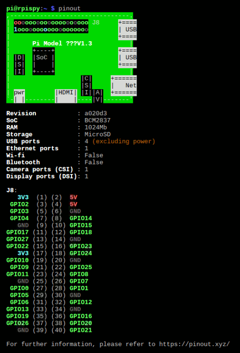
Checking Your Raspberry Pi's Hardware Layout
Because there are multiple versions of the Raspberry Pi, the layout of
the General Purpose Input/Output (G.P.I.O.) Pins differ. A quick way
to find out how the G.P.I.O. pins are laid out, for the Pi you are
currently working on, is to open a terminal and entering the following
command pinout.
Doing this will lead to you seeing something similar to the image below,
More information about this can be found at the following URL:
- [Checking Raspberry Pi Board Version](https://www.raspberrypi-spy.co.uk/2012/09/checking-your-raspberry-pi-board-version/][Raspberry Pi Board Information)
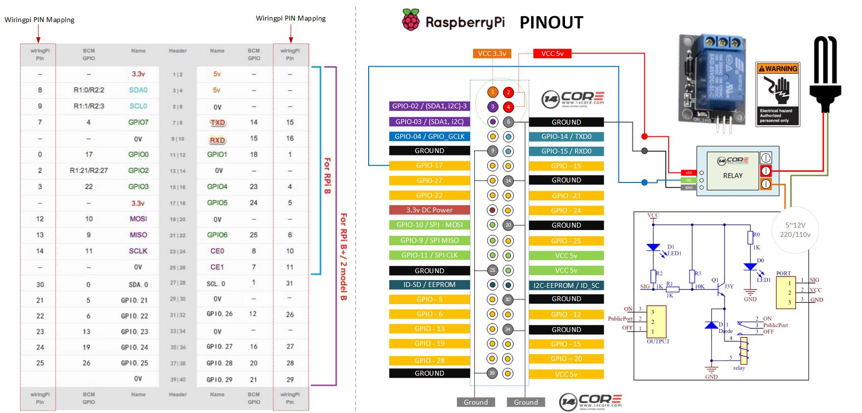
Wiring-Up the Relay
I used this article/blog post (linked above) as a starting-point for the relay part of the project. It includes software written in C and Python but I have stuck to just Python for this project. You can see how the relay is wired-up to the Pi in the image below.
#+Caption: Wiring Diagram for the Relay Project
#+Name: wiring-diagram-relay
General Overview of Controlling Relays
This is a primer for understanding how to control relays and the various types of relays at your disposal. The list is not exhaustive but is enough to get you going.
I find the guy in this video difficult to understand but he gets his message across well enough. He explains how a relay works and how to connect it to an Arduino Board and control a light bulb. If you are not familiar with how relays work, this video should give you a good grounding in it. /Note: This video does not use a Raspberry Pi so the information is limited to just the relay and the light part of the project.
The link above focuses on using an Arduino Board but you can determine what pin does what. The example in the link, also, includes a thermistor in its set-up which does not apply to this project. The image below is taken from the site and highlights what each pin is.
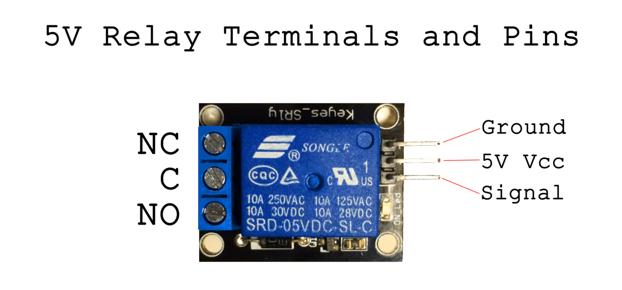
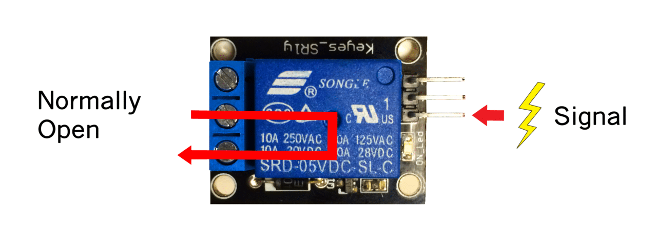
- NO (Normally Open): In the normally open configuration, when the relay receives a HIGH signal the 120-240V switch closes and allows current to flow from the C terminal to the NO terminal. A LOW signal deactivates the relay and stops the current. So if you want the HIGH signal to turn ON the relay, use the normally open terminal. See /figure no-configuration/ for further information.
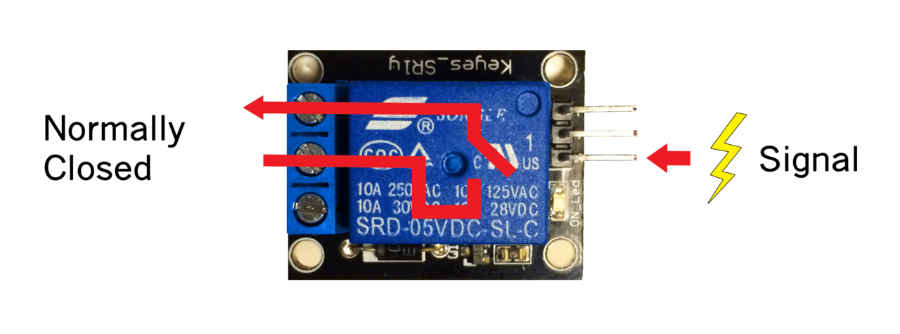
- NC (Normally Closed): In the normally closed configuration, a HIGH signal opens the switch and interrupts the 120-240V current. A LOW signal closes the switch and allows current to flow from the C terminal to the NC terminal. Therefore, if you want the HIGH signal to turn OFF the 120-240V current, use the normally closed terminal. See /figure nc-configuration/ for further information.
Project Set-up
This section needs to be written.